
In a past article here, we discussed many of the different gears that LEGO has available for use. In today’s article, we will talk about different ways to maximize your gear train. Gear trains can serve different purposes. One is to simply allow rotation movement at a location away from your motor itself. Another purpose for gear trains is to “gear up” to increase rotational speed or to “gear down” to increase torque. Depending on what the gear train needs to accomplish, you need to find and place the appropriate gears! Keep reading to see how!
Changing the location of rotation
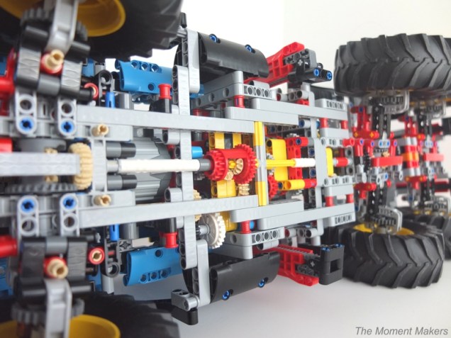
Many times in building with LEGOs, the physical motor does not fit into a model at the exact position where rotational motion is wanted to occur. An example could be a motorized Technic model in which the motor needs to make the drive wheels turn, but the Power Functions or Powered Up motor does not fit exactly in line with the drive wheel axles. In the picture above, the gears transfer the motion from the motor in the front all the way across the bottom of the truck.

There are several ways to change the location of the rotational movement to where you need it. The most common way to do this is by using a gear train. You can make a gear train by selecting gears that mesh together to form a path from the motor to the desired location. There are other websites that have gear calculators to help you find gears that will mesh. Often, though, it is best to learn by experimentation yourself. A new piece that came out this past year with the SPIKE Prime sets is a yellow Technic 11×19 base frame (Lego part number 39369). This piece can be an immense help in experimenting with gear combinations, as seen above. If you do not have this piece, though, you can improvise by using 15-long beams and potentially connecting them together.
One disadvantage to using many gears in a gear train is gear slippage. This refers to the fact that the gears each have a little bit of “slop,” in that you can turn a gear just a little before it causes the next gear to begin to turn at all. When all the gears are ready to turn, the gear train is “loaded” and slop isn’t an issue with that direction. This gear slippage is almost unnoticeable with a short gear train (few gears involved). However, as you add more and more gears, this slippage will begin to add up. It can make your lever arm or whatever other mechanism that you control at the end of the gear train to be less precise in its location.
Two other methods of transferring the location of rotation involve using chains or pulley wheels with bands. The LEGO chains come in various sizes and are sometimes even used as treads. The individual links are snapped together to make the chain your desired length. The chains have the advantage of turning one notch for one notch (slippage is little of an issue); the chain links coming apart could be a little bit of a concern depending on your model or robot design. Pulley wheels with belts are also a popular way to transfer motion (used often in LEGO Simple Machines and LEGO WeDo lessons). The pulley belts look a lot like rubber bands, but they are not quite as elastic. The different colors of the pulley belts correspond to the size diameter of the belt. One thing to remember with pulley belts is that they will slip under stress. If you have a task that requires a lot of torque, pulley belts may not be the best option for you.

Driver gear, idler gear, and follower gear

In a gear train, the driver gear is the one that motion is transferred from. The idler gear(s) transfers the movement from one gear to another — so this is just a gear in the middle of your gear train. As long as the gears mesh based on their size and location, it does not really matter what size the idler gear is. It is just an intermediary gear; its axle is not connected to a mechanism. Depending on how far the location of the rotational movement must be transferred, you may need the one or more idler gears, or alternatively you will need to use a pulley belt or chain as described above.
The follower gear is the one to which the motion is transferred. In every gear train you will have a driver gear and a follower gear (sometimes called a driven gear). The driver gear’s axle often connects directly to a motor or a hand crank. The follower gear’s axle typically connects to the mechanism that you want to move, whether it is a wheel to turn, a lever arm to rotate, etc. Gear trains can also aide in making your mechanism go faster (with less mechanical advantage) or slower (with more mechanical advantage). Again, we will discuss how in the “gearing up” and “gearing down” sections next.
Keep in mind with gear trains that each new gear you add will turn a different direction, as shown above. If you have an odd number of total gears in your gear train, the original driver gear will turn in the same direction as the final follower gear. However, if you have an even number of total gears in your gear train, the original driver gear will turn in the opposite direction as the final follower gear. Remember to account for what direction the mechanism needs to turn.
Gearing up
Gearing up is something you should do if you want to make your gear train’s output faster. How do you gear up? Gearing up is just another way to arrange gears to maximize performance.

In order to gear up, the driver gear, as shown in the picture, needs to be bigger than the follower gear. For every rotation the big gear makes, the smaller gear makes more rotations. Depending on how different the gears are in size, the follower gear could move very fast. You can calculate how much faster the gear train will move by counting the number of teeth on each gear (You can find all of the part numbers and number of teeth of each gear in Gears: Types of Gears). For example, the gear train above is moving at a 28 to 20 ratio or 7:5 because the driver gear has 28 teeth and the follower gear has 20. In knowing the ratio, we can know, that in the gear train above, that the black gear will move seven rotations for every five rotations of the driver gear with the crank, or 140% of the speed your hand turned the crank originally. With the increased speed, there is a sacrifice. Gearing up sacrifices mechanical advantage; your mechanism will not have the same strength as before you “geared up.”
Gearing Down

Gearing down is just the reverse of gearing up. Gearing down will make the end product slower and stronger. Since the driver gear has 20 teeth the follower gear has 28 teeth, the gray gear will move 20:28, 5:7, or ≈71% of what your hand turned the crank originally. Though gearing down makes your mechanism slower, sometimes it is necessary in order to complete the task that requires strength. If you are asking your mechanism to accomplish more than it has the torque to do, the gears will start slipping past each other or the motor will stall. You will know when your gears slip past each other because it makes a clicking sound. Make sure to stop your mechanism immediately when you hear gears clicking because the gears are actually grinding! This can cause long term damage to your gears.
Tying it together
Remember the picture above from the section “Driver gear, idler gear, and follower gear.” Currently, in the picture above, the input and output speeds are the same, but the speed of the idler gear is different. Why?
Recall the previous sections on gearing up and gearing down. Both the driver gear and the follower gear have 20 teeth. The idler gear has 12 teeth. Since the tan driver gear is bigger than the black idler gear, the idler gear will move faster. Also, since the black idler gear is smaller than the tan follower gear, the follower gear will move slower.
The speed of the input and the output is the same because the speed is balanced out. If the driver gear and the follower gear are the same size, the output of the follower gear will be the same as inputed originally. Just remember the direction depends on how many gears are in your gear train (odd number = same direction as input, even number = opposite direction as input). Thank you for reading this article! We hope it helped you with your gear trains!

2 thoughts on “Gears: Gear Trains”
Comments are closed.