
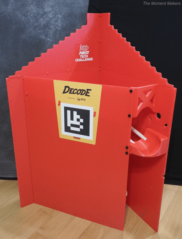
DECODE was an exhilarating season! We could not wait to bring some of that excitement to our outreach events, allowing both adults and young children to drive our robot around and launch “artifact” balls into the goal with automated aiming. The challenge, however, is that the DECODE goal structure from the field kit is simply too large to transport to outreach events. Additionally, the classifier is too large for the 4ft by 4ft field set-up (4 foam tiles) that we are often limited to in floorspace for many of our events. We decided to adapt the DECODE goal to make it smaller for transport, starting with removing the classifier ramp while still having an “artifact” ball chute. In this article, we link to the 3D files to print the parts that we designed, and we go through the process of assembling the adapted goal. We hope your team finds these goal modifications helpful in your own outreach events!
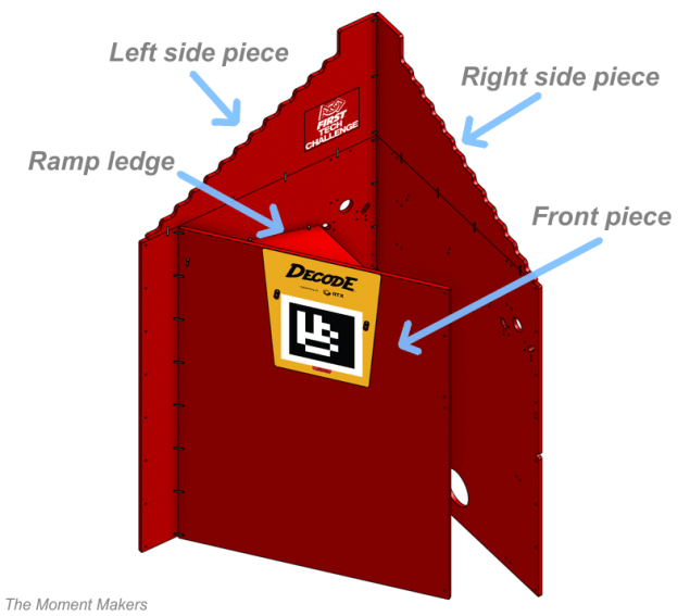
Goal Part Key
To make these instructions easier to understand, here is a brief key:
● The left side piece of the goal is the large part with the FIRST Tech Challenge logo (the jagged top piece and large rectangle piece that are connected)
● The right side piece is the large part without the FIRST Tech Challenge logo (the jagged top piece and large rectangle piece that are connected)
● The front piece is the large part with the DECODE title and AprilTag
● The ramp ledge is the triangle-shaped piece inside the goal that would previously be used to redirect balls toward the classifier ramp
Design
Overall Constraints
- We wanted all of the corrugated plastic parts to fold flat for storage and transport; this requires removing the metal extrusion ramp and classifier.
- We needed to design a replacement for the ramp to allow the balls to roll off nicely back onto the field, as opposed to just falling onto the floor.
- To maximize efficiency in set-up and take-down, we wanted all of our designed parts to be easily mounted using thumbscrews for faster assembly.
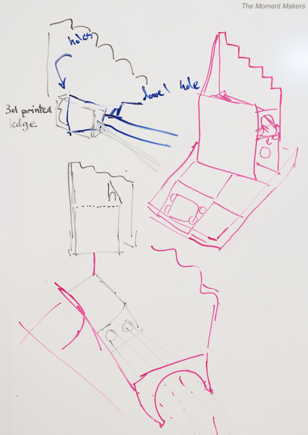
We sketched various design ideas:
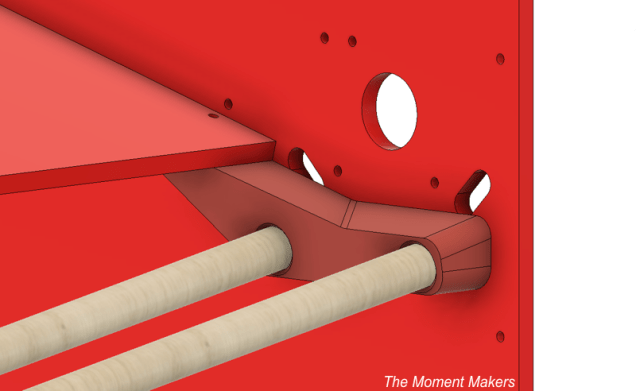
Back Dowel Holder
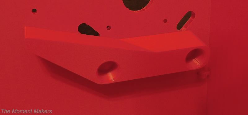
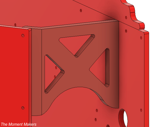
After looking at the goal and what the original ramp extrusion sought to achieve, we decided on several requirements for designing a back corner part:
- We wanted to use two wooden dowels (in place of the original metal ramp extrusions) to guide the ball to the chute. We needed to design a part to mount these dowels to the right of the ramp ledge.
- Using the existing holes in the left side piece, we needed to design matching holes into our 3D-printed part to allow mounting.
- We needed the part to hold the ramp ledge of the goal to allow support without zip-ties.
So, we sketched and modeled what we thought the part could look like and voted on which design we wanted. Afterwards, we made some small changes to it and had it printed. Once that process was done, we inserted heat set nuts into the part and attached it to the goal using two thumbscrews.
Chute
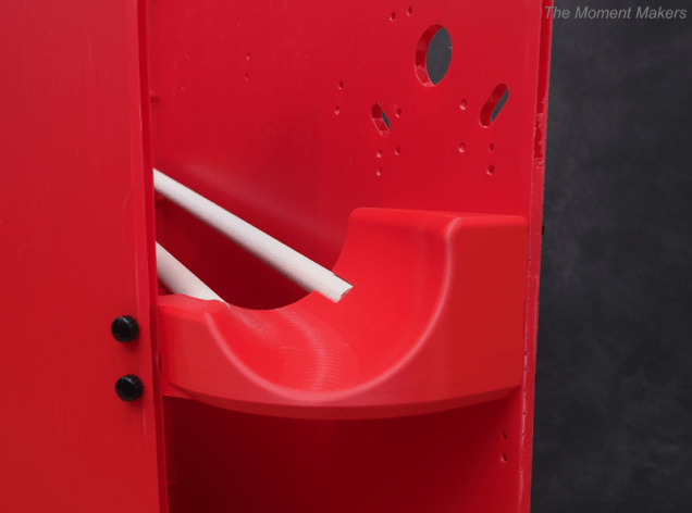
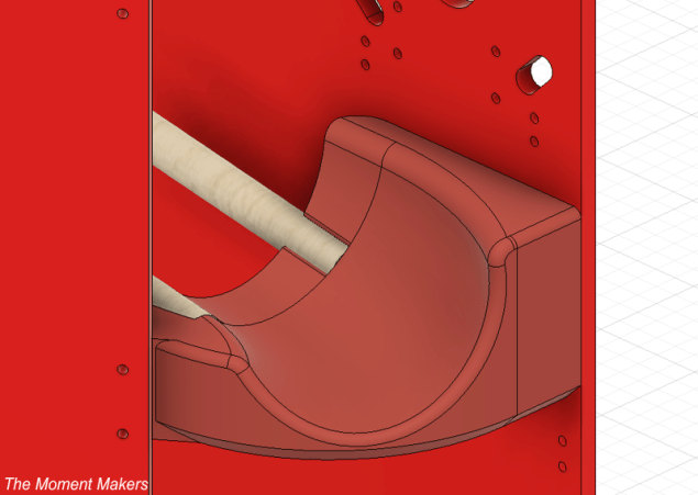
We decided on several requirements for designing the chute:
- Because we planned to position the goal outside one of the perimeter walls of the 4ft x 4ft field, the end chute needed to act as a small angled slide to redirect balls back onto the field.
- The chute needed to hold the other end of the two dowels.
- The part needed to be attached to the goal using thumbscrews connecting to the existing corrugated plastic front piece and right side piece holes.
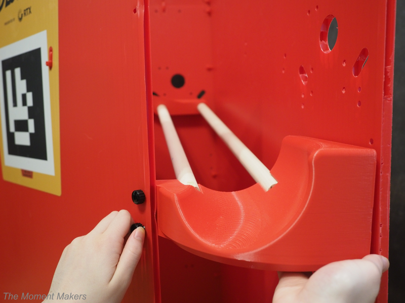
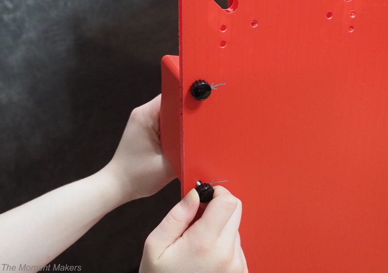
To make the chute, we worked together on the part, sharing our thoughts and ideas to form one design that we all agreed on. When it finished printing, we inserted heat sets and screwed four thumbscrews into the sides of the part.
Arch
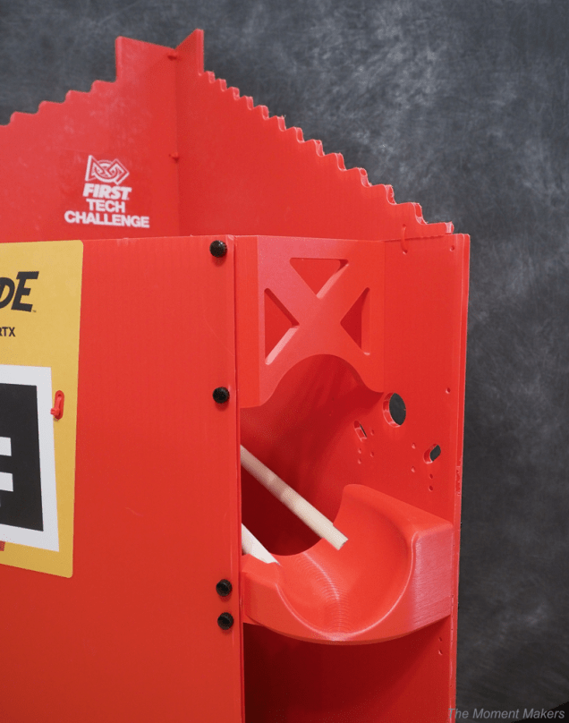
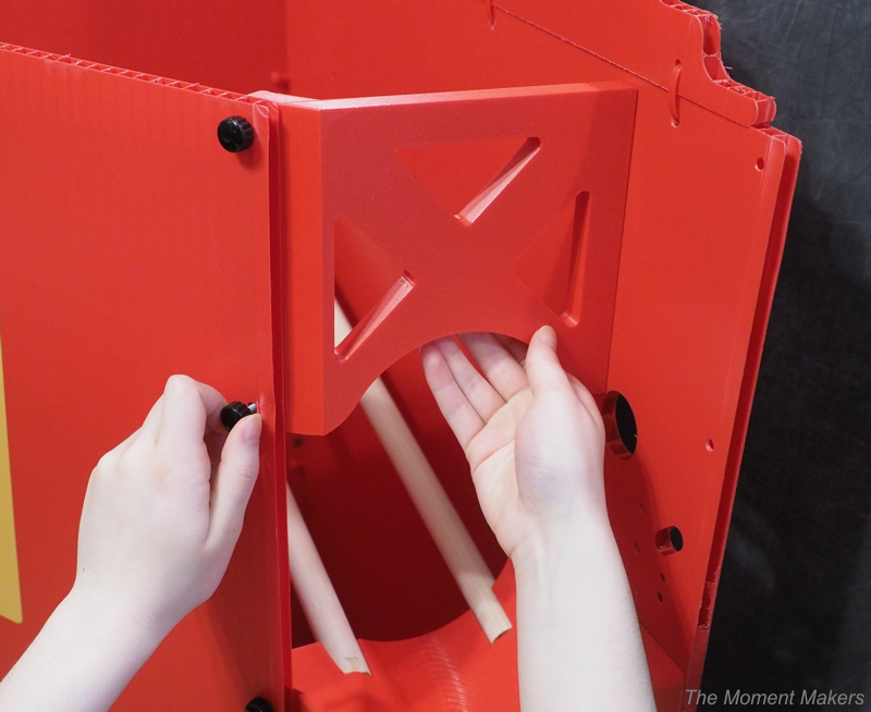
We had previously removed the original corrugated plastic arch so that the goal could fold and no additional zip-ties would be needed for re-assembly at each event. Even with our two other printed parts, balls would still occasionally bounce out of the field where the arch would have been. Therefore, we decided to make a 3D-printed arch instead so that it could:
- Be assembled using the existing corrugated plastic front piece and right side piece holes with thumbscrews instead of zip-ties.
- Act as more of a backboard to ensure that balls do not come flying out of the goal too high (resulting in balls leaving the field).
We designed the part, got it printed, put in the heat-set nuts, and screwed in four thumbscrews to secure it.
Assembly Process
Here is the process of how to construct our revised outreach goal. We will be explaining these instructions using the red goal, but a blue goal could be assembled identically but mirrored.

Parts Needed
The build requires:
● The red goal with all hardware removed (the classifier, ramp, and aluminum clips are detached)
● Our three 3D-printed parts (linked at the end of the article)
● 10 M4 thumbscrews (14-24 mm in screw length) found on Amazon or from hardware suppliers
● 2 wooden dowels (7/8″ diameter, cut to 21-21.5″ length) from craft or hardware stores
● 16 replacement zip-ties
Zip-ties
To allow the goal to be folded flat for transport and storage to take up less space, we cut some of the pre-existing zip-ties to open up the goal and replaced some of them with newer ties so that the corners and the joints would not be too tight.
- Cut the zip-ties securing the corrugated plastic arch piece. We do not use this arch piece for our adapted goal since it prevents it from folding.
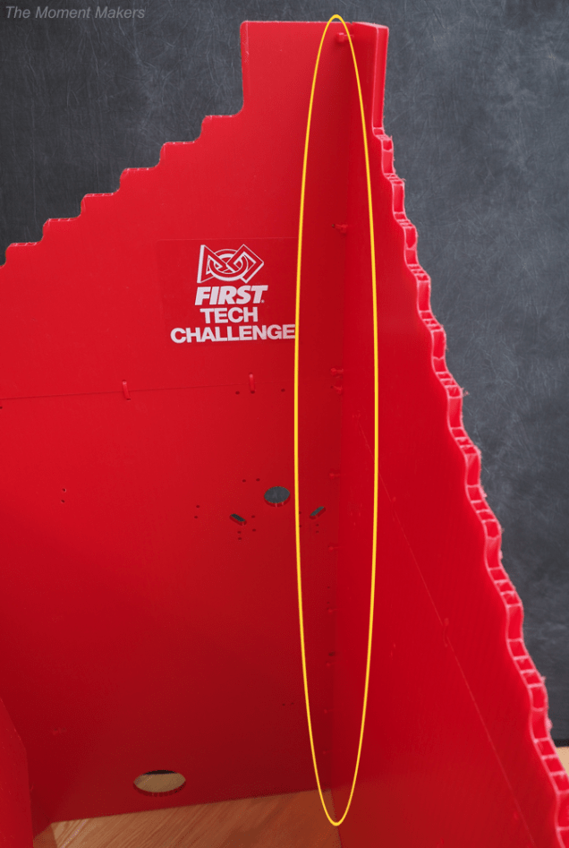
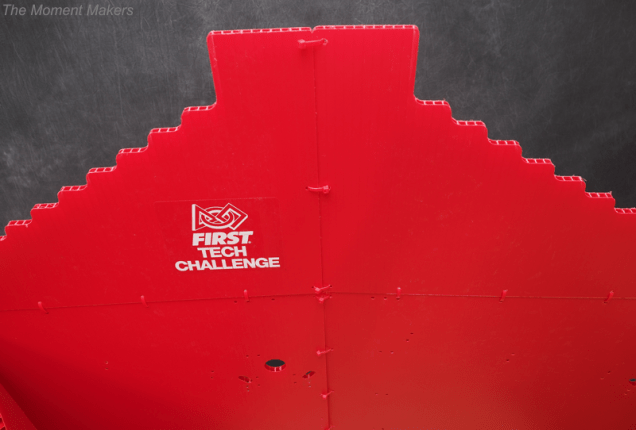
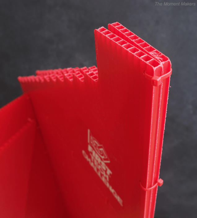
- Cut the 11 zip-ties connecting the back corner of the goal (between the left and right side pieces). Install new zip-ties in the same places, and make these significantly looser so that the right side piece can fold back (flat) behind the left side piece.
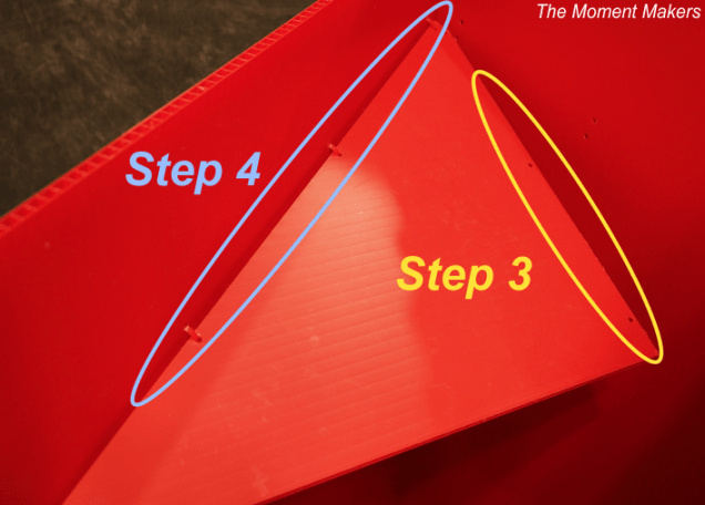
- Cut the 3 zip-ties connecting the ramp ledge to the left side piece. These zip-ties will not be replaced so that this flap can also fold down toward the front piece for storage/transportation.
- Cut the 3 zip-ties connecting the ramp flap to the front piece. Install new zip-ties in the same places, and make these significantly looser so that the ramp ledge can fold flat against the front piece.
- Cut the top two zip-ties connecting the front piece to the left side piece. Install new zip-ties in the same places, and make these significantly looser so that the front piece can fold flat against the left side piece (the ramp flap should be able to fit between the front piece and the left side piece, and these pieces should be able to stay flat together when folded).
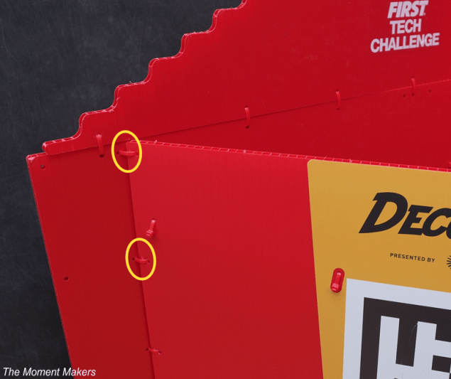
- Next, unfold the goal back to its normal configuration so that the 3D-printed parts can be installed.
Back Dowel Holder
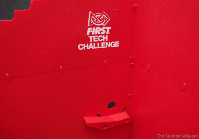
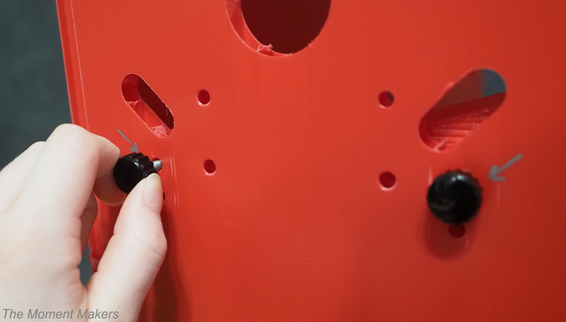
To mount the back dowel holder, hold the part up against the inside wall of the left side piece below the large circle. Put the thumbscrews through the holes beneath the pill-shaped ones to mount it.
Chute
- Fold the goal such that the ramp ledge rests on top of the shelf of the back dowel holder.
- Insert the wooden dowels into the indentations in the back dowel holder.
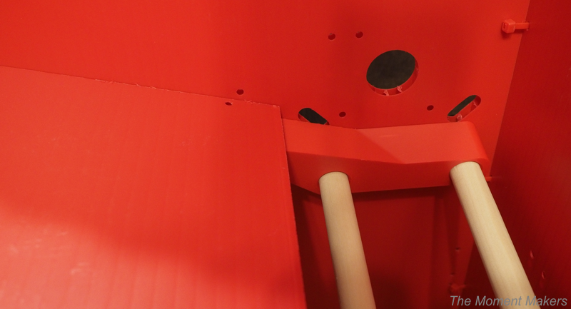
- Carefully slot the chute onto the other end of the dowels.
- Secure the part with thumbscrews in their respective holes (2 thumbscrews in the front piece and 2 in the right side piece).
Arch
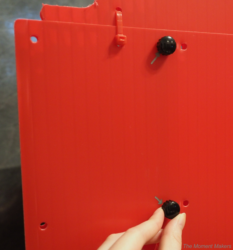
Hold the arch in the front of the goal above the chute and secure the arch with thumbscrews in their respective holes (2 thumbscrews in the front piece and 2 in the right side piece).
Goal Placement
We personally place our adapted goal outside of one of our perimeter wall sections on a 4ft x 4ft field for outreach. If your event allows for a larger field size, you could also place the goal inside the field itself (more similar to the official DECODE season).
3D Files
Our updated goal has already helped us, so we hope that you will be able to use it, too!
https://www.printables.com/model/1792030-adapted-ftc-decode-goal-for-outreach-19502


You must be logged in to post a comment.